This article is based on Robert C. Martin's book "Agile Principles Patterns and Practices in C#". I have summarized what I personally find most important when creating UML class diagrams.
UML class diagrams allow us to denote the static contents ofand the relationships betweenclasses. In a class diagram, we can show the member variables and member functions of a class. We can also show whether one class inherits from another or whether it holds a reference to another. In short, we can depict all the source code dependencies between classes.
This can be valuable. It can be much easier to evaluate the dependency structure of a system from a diagram than from source code. Diagrams make certain dependency structures visible. We can see dependency cycles and determine how best to break them. We can see when abstract classes depend on concrete classes and can determine a strategy for rerouting such dependencies.
Classes
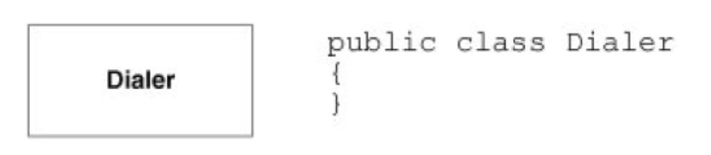
The following image shows the simplest form of class diagram. The class named Dialer is represented as a
simple rectangle. This diagram represents nothing more than the code shown to its right.
A class icon can be subdivided into compartments. The top compartment is for the name of the class; the second, for the variables of the class; and the third, is for the methods of the class. The following image shows these compartments and how they translate into code.
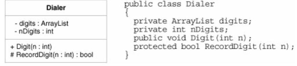
This kind of detail is sometimes useful but should not be used very often. UML diagrams are not the place to declare variables and functions. Such declarations are better done in source code. Use these adornments only when they are essential to the purpose of the diagram.
Association
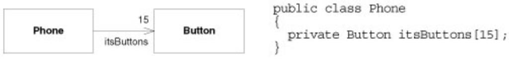
Associations between classes most often represent instance variables that hold references to other objects. For example, The next image shows an association between Phone and Button. The direction of the arrow indicates that Phone holds a reference to Button. The name near the arrowhead is the name of the instance variable. The number near the arrowhead indicates how many references are held.
Inheritance
You have to be very careful with your arrowheads in UML. The next image shows why. The arrowhead pointing at Employee denotes inheritance. If you draw your arrowheads carelessly, it may be difficult to tell whether you mean inheritance or association. To make it clearer, I often make inheritance relationships vertical and associations horizontal.
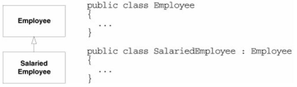
In UML, all arrowheads point in the direction of source code dependency. Since it is the SalariedEmployee class that mentions the name of Employee, the arrowhead points at Employee. So, in UML, inheritance arrows point at the base class.
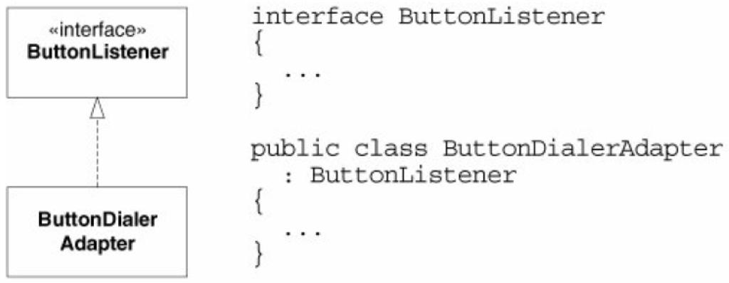
UML has a special notation for the kind of inheritance used between a C# class and a C# interface. As shown in the next image, it is a dashed inheritance arrow. In the diagrams to come, you'll probably catch me forgetting to dash the arrows that point to interfaces. I suggest that you forget to dash the arrows that you draw on whiteboards, too. Life's too short to be dashing arrows.
Aggregation
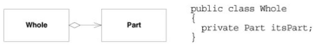
Aggregation is a special form of association that connotes a whole/part relationship. The next image shows how it is drawn and implemented. Note that the implementation shown is indistinguishable from association. That's a hint.
Unfortunately, UML does not provide a strong definition for this relationship. This leads to confusion because various programmers and analysts adopt their own pet definitions for the relationship. For that reason, I don't use the relationship at all, and I recommend that you avoid it as well. In fact, this relationship was almost dropped from UML 2.0.
Composition
Composition is a special form of aggregation, as shown in Figure 19-16. Again, note that the implementation is indistinguishable from association. This time, however, the reason is that the relationship does not have a lot of use in a C# program. C++ programmers, on the other hand, find a lot of use for it.
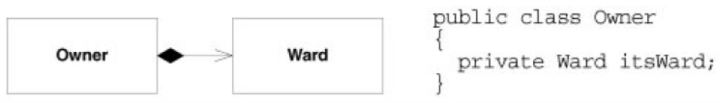
The owner is responsible for the lifetime of the ward. If the owner is destroyed, the ward must be destroyed with it. If the owner is copied, the ward must be copied with it. In C#, destruction happens behind the scenes by the garbage collector, so there is seldom a need to manage the lifetime of an object.
Multiplicity
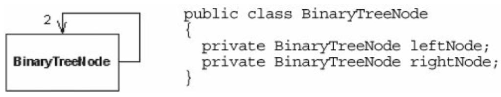
Objects can hold arrays or collections of other objects, or they can hold many of the same kind of objects in separate instance variables. In UML, this can be shown by placing a multiplicity expression on the far end of the association. Multiplicity expressions can be simple numbers, ranges, or a combination of both. For example, the following image shows a BinaryTreeNode, using a multiplicity of 2.
Association Stereotypes
Associations can be labeled with stereotypes that change their meaning. The next image shows the ones that are used more often.
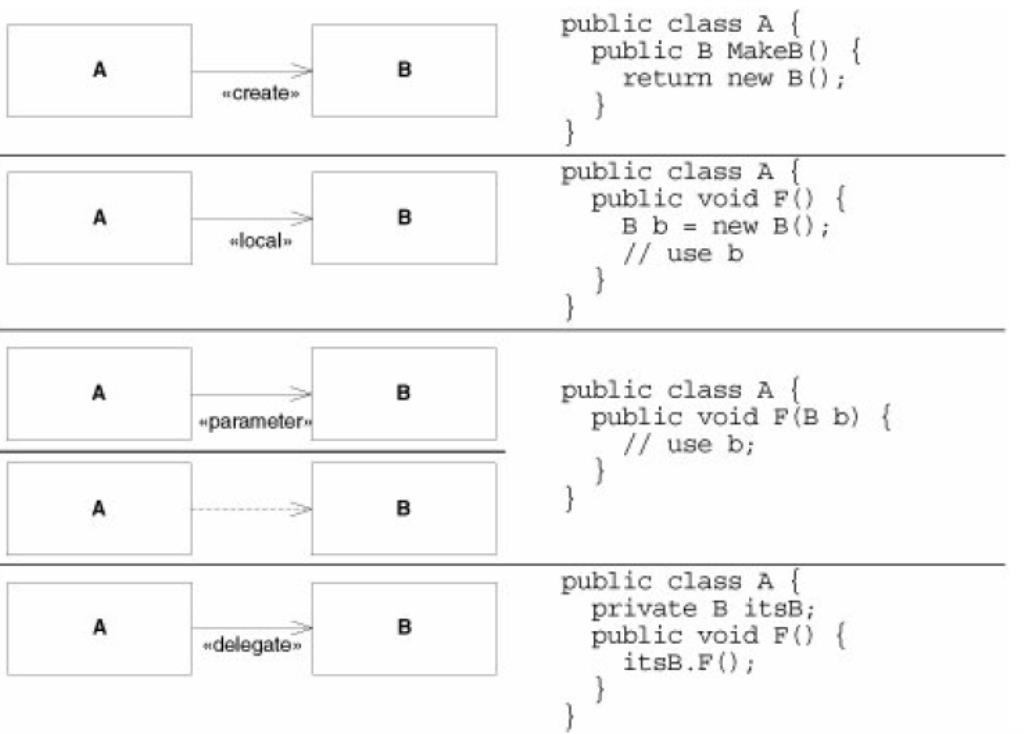
The «create» stereotype indicates that the target of the association is created by the source. The implication is that the source creates the target and then passes it around to other parts of the system. In the example, I've shown a typical factory.
The «local» stereotype is used when the source class creates an instance of the target and holds it in a local variable. The implication is that the created instance does not survive the member function that creates it. Thus, it is not held by any instance variable or passed around the system in any way.
The «parameter» stereotype shows that the source class gains access to the target instance though the parameter of one of its member functions. Again, the implication is that the source forgets all about this object once the member function returns. The target is not saved in an instance variable. Using dashed dependency arrows, as the diagram shows, is a common and convenient idiom for denoting parameters. I usually prefer it to using the «parameter» stereotype.
The «delegate» stereotype is used when the source class forwards a member function invocation to the target. A number of design patterns apply this technique: PROXY, DECORATOR, and COMPOSITE. Since I use these patterns a lot, I find the notation helpful.
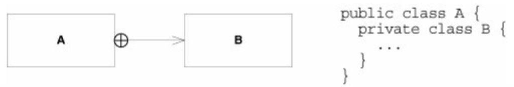
Nested Classes
Nested classes are represented in UML with an association adorned with a crossed circle, as shown in the next image:
Association Qualifiers
Association qualifiers are used when the association is implemented through some kind of key or token instead of with a normal C# reference. The example in in the next image shows a LoginTransaction associated with an Employee. The association is mediated by a member variable named empid, which contains the database key for the Employee.
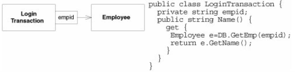
This notation is useful in rare situations. Sometimes, it's convenient to show that an object is associated to another through a database or dictionary key. It is important, however, that all the parties reading the diagram know how the qualifier is used to access the object. This is not something that's immediately evident from the notation.
Conclusion
UML has lots of widgets, adornments etc. There are so many that you can spend a long time becoming an UML language lawyer, enabling you to do what all lawyers can: write documents nobody else can understand.
In this article, I have avoided most of the some features of UML which are not used that often. Rather, I have shown you the parts of UML that I are most commonly used. Using too little of UML is almost always better than using too much.
IT
uml class diagrams
21.01.2020
Acasa